 One of the major advantages of creating and using Building Information Modeling (BIM) for a project is to move information across multiple players of the project. As its name suggests, a typical BIM entity possesses properties such as length, height, width, color, texture, levels etc as well as behaviors that direct and alter these properties. This behavior can be controlled by generating a parametric design. This facilitates altering and enhancing the building design and construction details in an easy and transparent manner. Revit 2010 offers opportunities to conceive, create, and use parametric families for this purpose. Furthermore, BIM differs from any other 3D building model in the way information relating to estimating, scheduling, energy simulation etc. is embedded in the model. Another advantage of BIM is to enable visualization of complex design and construction details related with building’s aesthetic, functional and environmental aspects for better understanding.
Purpose

Among current trends in architectural design is to introduce sustainability by either applying energy saving strategies or incorporating renewable energy options. One dilemma faced by building designers is to create a balance between aesthetics and technology. One among most practiced is Building Integrated Photovoltaic (BiPV) that involves integrating solar cells or modules in building components such as walls, pergolas, roofs etc. Studies suggest that BiPVs not only facilitate generating renewable energy but also, protect buildings form heat, cold and rain. Furthermore, BiPVs may be more cost effective if they replace building components such as wall cladding panels, roof slates, light shelves, sun-shades etc. Renewable energy components such as solar PVs often influence the aesthetic quality of the building adversely and hence; need to be analyzed for their possible impact on building form and aesthetics. Studies suggested considering both technological and aesthetic factors while integrating such renewable technologies into buildings. Furthermore, flexibility of size, color, texture and also cost in PV modules is recommended for better integration of solar modules into a building.
Objectives
In this project two-roof based families are created using a generic PV panel. It was expected that the PV panel would change its angle in horizontal plane (azimuth) and in vertical plane (Altitude) based on user input time. Furthermore, user can change its size also. This generic PV panel is nested to multiple families to create a sloping roof and a pergola family. Three objectives were kept in mind while creating these families:
- Parameterizing the host and nested families in such a manner that host family governs the properties and behavior of the nested families
- Creating a database example of sun’s position in terms of its azimuth and altitude to indicate possible sun position database
- Deriving a code in C# that enables users to input desired time in a window’s form to calculate azimuth and altitude angles
- Creating an Application Programming Interface (API) between the database and Revit Architecture 2010
A series of parametric families are nested to the main roof family parameters of which control the behavior of these nested families. Solar PV panels are assumed as solar tiles that can be installed on roof surfaces. This family would help building designers to visualize behavior of all of the solar tiles together especially when these are sun-tracking, as their movement would differ with changing sun positions. Building designers would be in a better position to visualize and analyze solar tiles on designed roof.
Creating Parametric Families
1. Sloping Roof
This is a standalone roof-based family that can be used on any sloping roof with one or two sides sloping. This roof assumes a sun-tracking PV array system modules of which are envisaged as roof tiles. The limitation of size for this family is >5’0” or more than or equal to any size directed by PV panel/module tile width. Enormous areas of flat as well as sloped roof surfaces can generate solar power using this system. There is no limitation for its maximum size, as this can be stretched to any extent. In this project these are considered being installed on south facing slope of the roof.
 |
| Sloping roof family structure: Nested and host families |
 |
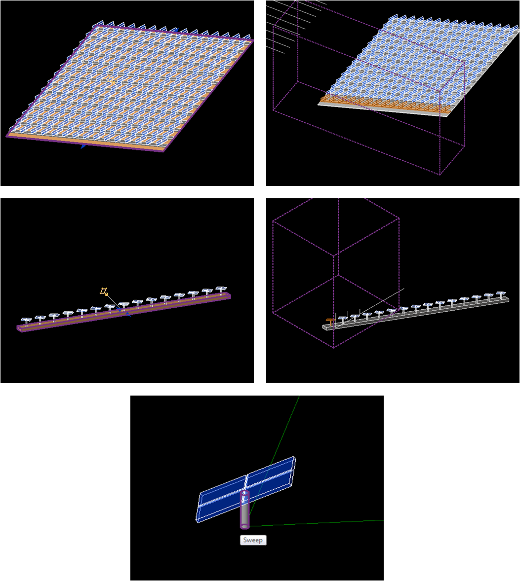
| Sun-tracking solar panel with its parametric design |
Task1. Task one included creating a solar PV panel that can rotate in horizontal as well as vertical plane. This was accomplished by drawing a reference line on horizontal plane as work plane and drawing another reference line at vertical plane of the earlier reference line as work plane. Their behavior is controlled by two angular dimensions. Solar PV panel is drawn on the smaller side plane as shown in figure by using sweep function. PV panel’s width and depth are parameterized within the sweep only in such a manner that both the dimensions change along panel’s central axis.
Task2. This task involves creating a metal joist/pipe that would hold multiple arrayed PV panels with cleats. Two parameters are important: angle of pipe and its length, as these two would be transferred to sloping roof. Material parameters for pipe are newly created and cleat and PV panel are transferred from the nested PV panel family. Blend function is used to make pipe that is constrained at two ends by reference planes as shown in figures below. Following parametric behaviors are expected:
- Size, angle and materials parameters would change based on change in length of pipe
- PV panel must maintain a preferred gap while changing their depths
- Reference planes on either sides to restrain first and last array elements would possess parametric dimensions with constraining reference plane to keep them in place
- At lower altitude panels may cast shadows on each other; hence panel size should be smaller
- Number of PV pipe array elements would adjust themselves with changing PV width as shown in figures below.
- Diagonal of PV panel should be used to separate them considering their movement in horizontal plane and possible clash
 |
| Each panel adjusting for their width based on diagonal size |
Task3. A roof is created using blend function just like the pipe in earlier task and earlier family is arrayed across roof length. All of the size, angle and material parameters are transferred to the main host family. Following figures demonstrate the main host family.

 |
| Section and 3D view of project 1 house with sloping roof PV family |
Purpose of this family is to enable designers to cover outdoor spaces such as patio, sidewalks, garden walks, parking spaces and plazas with a pergola whose louvers are in the form of solar PV panels. These panels would cast light and shadow on covered surfaces making them comfortable to walk or to sit during hot and cold months. Solar PV would be generating power to cater to building needs.

This family is a standalone parametric family that can be used in the outdoors spaces of any size. A minimum width of 12 feet is required for this, however; there is no limitation for its maximum length or width. The main host family is made of multiple nested families each of which has its own properties and parametric behavior. Each time a nested family is nested again in another host family parameters related to size, angle and materials are transferred. Only those parameters are transferred that demonstrate maximum control over family’s other parameters. This way only few parameters in host family can control nearly all of the parameters in all of the nested families. Figure above illustrates a structure of host and nested families.


 |
| Figures showing nested and host families |
Following aspects were considered before developing this standalone family:
Architectural aspects: This family contains column family proportion of which is important to consider, as users may have different sizes of spaces. Hence, if length or height of pergola module is changed, its column’s proportions (height to column diameter and other elements on the column) should also change based on certain proportion rule.
Architectural aspects: This family contains column family proportion of which is important to consider, as users may have different sizes of spaces. Hence, if length or height of pergola module is changed, its column’s proportions (height to column diameter and other elements on the column) should also change based on certain proportion rule.
 |
| Column proportion changing with column height |
 |
| Pipe Thickness and depth changing with a change in span |
Structural aspects: There exist structural members such as pipes and columns whose size depends on the span pergola covers. Hence, if pergola possess larger span depth and thickness of horizontal load-bearing pipe must change. In this case a thumb rule of 1/16th of the total span is used as a rule. However, building designers can embed any such rule depending on their structural requirements.
 |
| Depth of pipe shown for a 15 ft. and 25 ft span |
Functional aspects: PV panels must not cast shadows on each other, as their size is relatively larger. However, if you determine the gap between two panels considering the lowest solar altitude, it would be impractical to design such a pergola. Therefore, a baseline of 20o is considered in this project to auto calculate the gap between two consecutive solar panels to avoid shadow casting. Any angle that is greater than 20o would be fine as there would be no chances of shadow casting between solar panels.
Furthermore, size of each PV panel can be changed to suit to designer’s project requirements. The gap between PV pipes in one pergola module is based on PV width, which also is modified automatically whenever a gap exists between them.
 |
| Pergola module with parametric PV stripes |
This family is developed by completing following tasks:
Task1. Just like the earlier sloping roof family, this family contains a generic PV panel, which is derived using similar procedures as described earlier. However, this PV prototype possesses a relatively larger dimension. Height of the PV panel could be changed, however; this was not accomplished in this project. The height of cleat that supports the panel is parametric and by constraining PV panel to top of this task can be accomplished. For this the slope of PV must match with sloping end of the cleat.
Task2. A pergola pipe is created using sweep function that has length, thickness and depth parameters. Furthermore, its angle can also be changed. PV panels with cleat are arrayed to form a stripe of PV panels whose length can be modified. To avoid mutual shadow casting, a baseline of 20 degrees for solar altitude is selected and this value is used in the formula as shown in figures below. For solar altitude more than 20 degrees, there will not be any problem of shadow casting. The thickness and depth of the pipe would change with its changing length based on one sixteenth rule as shown in figures above.
 |
| Development of pergola pipe with PV panels |
Task3. A module of array of PV pipes created in task 2 is developed that enables user to define a module of certain length and width with PV pipes arrayed in between. The gap of these pipes would depend on width of PV panel. PV panels would accommodate any surplus gap that remains.
Task 4. In this task, a column family is created first that includes column height and its radius parameters. The height of column governs the radius and height of top and bottom reveals. I used my own rule of proportion for this, however; user can create and input own rules. Finally, a row of columns is developed with arrayed column elements where gap between two columns is controlled by host family as shown in figures below.
 |
| Pergola family as loaded in a project |
 |
| A bird's eye view of pergola family |
Task 5. Finally a stripe of pergola modules is developed and arrayed to form a pergola family whose length and width parameters change and govern all of the nested family’s parameters. The angle of PV panels can also change in all of the modules. This main family is developed in such a manner that while arraying there remains no gap between two arrayed pergola module elements.
Please see next post for API development for this project or Click here
Please see next post for API development for this project or Click here
Thanks for sharing, really enjoyed this article, look forward to coming back and reading more
ReplyDeleteResidential Solar Power
Solar Las Vegas